
Why Reciprocating Grate Boilers Handle High-Moisture Biomass Better Than Conventional Designs
Switching to biomass is one of the most effective ways to cut fuel cost and emissions in industrial steam generation — but real-world biomass rarely arrives dry and uniform. Freshly harvested forestry waste, wet sugarcane bagasse, palm oil empty fruit bunches, and outdoor-stored agricultural stalks routinely carry moisture levels of 40% to over 60%. Feed that fuel into a boiler that wasn’t engineered for it, and the results are predictable: unstable flames, severe unburned carbon losses, clinkering, capacity derating, and frequent shutdown cycles. Reciprocating grate boilers are specifically engineered to eliminate these problems. This guide explains the mechanical and thermal principles behind why, compares the technology directly against conventional alternatives, and covers the operating practices that get the most out of genuinely wet fuel.
Why High Moisture Breaks Conventional Combustion
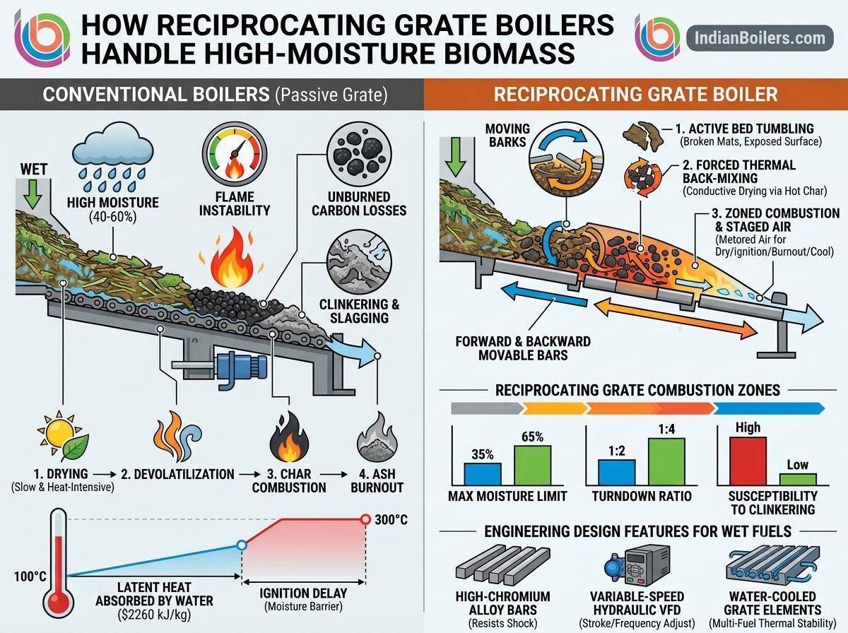
Solid fuel combustion happens in four sequential stages: drying (evaporating moisture), devolatilization (releasing volatile gases), char combustion (oxidizing fixed carbon), and ash burnout (discharging spent ash). When fuel moisture exceeds roughly 35–40%, the drying stage consumes a disproportionate share of available heat before the fuel can even begin to ignite.
The physics here is unforgiving: water requires approximately 2,260 kJ/kg (540 kcal/kg) of thermal energy simply to convert from liquid into vapor — energy that produces no useful steam output, just moisture removal. Liquid water in the fuel matrix pins the particle surface temperature at 100°C until that moisture fully evaporates, and volatiles can’t escape or ignite until the fuel reaches roughly 200–300°C. Meanwhile, the evaporated moisture expands dramatically into steam inside the furnace, diluting oxygen concentration and cooling the combustion zone locally. In boilers where fuel moves passively — resting on a static bed or conveyor — this extended drying phase smothers the ignition zone entirely, leading to flame failure and unburned fuel dumping straight into the ash pit.
How Reciprocating Grates Solve the Problem Mechanically
A reciprocating grate consists of alternating rows of fixed and movable heat-resistant alloy grate bars. Hydraulic or mechanical actuators drive the movable bars in a controlled forward-and-backward stroke over the fixed bars — a continuous push-and-pull motion that fundamentally changes how wet fuel behaves inside the furnace, through three distinct mechanisms.
Active Fuel Bed Tumbling and Mechanical Shearing
Unlike a travelling grate, where fuel rests passively on a moving conveyor, a reciprocating grate subjects the fuel layer to continuous tumbling and shearing. Wet biomass particles frequently cling together into thick, dense mats — as the reciprocating bars push and slide beneath the bed, they break up these clumps and continuously expose fresh, unevaporated inner surfaces to furnace heat, while also eliminating the stagnant pockets of wet fuel that would otherwise block airflow and smother primary flames.
Forced Thermal Back-Mixing
The defining mechanical feature of pushing-type and reverse-reciprocating designs is genuine internal fuel back-mixing: as movable bars stroke backward, a portion of fully glowing, ignited char from the main burning zone gets pushed back into the incoming stream of raw, wet biomass. This gives wet fuel direct heat conduction from hot char particles mixed directly into it, rather than depending solely on slower radiant heat from refractories — accelerating drying and triggering rapid ignition even at 50–60% fuel moisture.
Zoned Combustion Control and Air Staging
Reciprocating grates use isolated air chambers beneath the grate surface, with primary air metered independently to match each combustion stage’s actual requirement: low-volume, high-temperature air (180–250°C) in the drying zone drives off surface moisture without cooling the fuel bed; moderate primary air combined with high-velocity over-fire air fuels rapid volatile burn-off in the devolatilization zone; high primary air volume ensures complete oxidation of remaining fixed carbon in the char zone; and reduced airflow in the final zone cools spent ash while recovering its sensible heat back into the combustion process.
A Direct Comparison Across Technologies
| Operational Parameter | Travelling/Chain Grate | Fluidized Bed (AFBC/CFBC) | Reciprocating Grate |
|---|---|---|---|
| Maximum moisture tolerance | 30–35% | 35–45% | 55–65% |
| Fuel bed agitation | None (passive conveying) | High (suspended in sand) | High (mechanical tumbling) |
| Susceptibility to clinkering | High (static bed) | High (bed agglomeration) | Extremely low (continuous shearing) |
| Fuel pre-treatment requirement | Shredded/uniform | Strict sizing (10–50mm) | Minimal (handles coarse, irregular fuel) |
| Turndown ratio | ~1:2 | ~1:3 | ~1:4 (superior part-load control) |
| Parasitic power draw | Low | High (high-pressure fans) | Moderate |
Versus Travelling Grates
When high-moisture biomass (above roughly 40%) is fed onto a travelling grate, fuel rests undisturbed in a dense layer, drying occurs slowly from top to bottom via radiation from the upper furnace arch alone, and because evaporation is slow, the ignition front reaches the grate’s far end very late in the cycle — often too late. Unburned, wet carbon reaches the discharge end and dumps directly into the ash pit, causing severe unburned carbon losses (commonly exceeding 10%) and forcing capacity derating. Reciprocating grates avoid this because mechanical shearing continuously churns the bed, exposing all surfaces to radiant heat and mixing hot char into raw wet fuel to ensure burnout completes before ash discharge.
Versus Fluidized Bed Boilers (AFBC/CFBC)
Fluidized bed combustion suspends fuel particles in a boiling bed of hot sand, offering strong heat transfer rates — but high-moisture biomass introduces genuine operational risk here too. Feeding wet biomass drains thermal energy directly from the sand bed, and if bed temperature drops below roughly 650°C, fluidization fails and the furnace can trip entirely. High alkali content (potassium and sodium) common in agricultural residues can also react with hot silica bed sand to form low-melting-point eutectic compounds that fuse the bed solid, requiring a costly manual shutdown to dig out. Fluidized beds additionally demand precise fuel sizing — coarse wet roots or long palm fronds block feed chokes and settle unburned at the bottom of the bed. Reciprocating grates sidestep both issues entirely: no sand bed means no agglomeration or defluidization risk, and the technology comfortably processes coarse, non-uniform biomass up to roughly 150–200mm long without choking.
Engineering Features That Make This Work at Scale
Not every reciprocating grate is built the same — handling genuinely high-moisture biomass reliably requires specific structural and thermal engineering:
High-chromium alloy grate bars. Combustion of wet biomass creates significant local thermal gradients as fuel transitions rapidly between wet and drying states. Grate bars cast from high-chromium steel alloys (commonly 25–28% chromium with nickel additions) resist thermal cracking, warpage, and high-temperature oxidation under this continuous stress.
Variable-speed hydraulic actuation. Grate movement driven by hydraulic cylinders with proportional valves and VFDs lets operators adjust in real time — shortening stroke intervals and increasing stroke length when fuel moisture rises to extend bed drying time and boost agitation, and reducing stroke speed when drier fuel enters to preserve bed depth and protect grate elements from overheating.
Water-cooled grate elements. For plants running multi-fuel blends — alternating between wet bagasse and dry wood pellets, for instance — standard air-cooled grates can overheat during high-temperature dry-fuel runs. Water-cooled reciprocating grates circulate boiler feedwater directly through internal channels inside the grate bars, absorbing thermal shock, maintaining stable grate metal temperature, and meaningfully extending component service life.
Four Operating Practices That Maximise Performance
Maintain primary air preheating (180–250°C). Never feed ambient-temperature air beneath a wet fuel bed. Multi-pass tubular air preheaters raising under-grate air temperature to this range immediately support moisture evaporation at the fuel inlet zone without pulling heat away from the core flame.
Optimise over-fire air turbulence. Since evaporating moisture dilutes volatile gas concentration in the lower furnace, injecting secondary and tertiary over-fire air through high-pressure nozzles at velocities of roughly 50–70 m/s creates the intense turbulent mixing needed to guarantee complete burn-off of CO and unburned hydrocarbons in the upper combustion zone.
Blend fuel based on moisture content. If incoming fuel moisture surges past roughly 60%, furnace temperature drops rapidly regardless of grate design. Blending ultra-wet fuel with drier biomass (wood chips or dry husk at 12–15% moisture) stabilises overall incoming moisture around 40–45%, using the formula: Target Moisture = [(M₁ × W₁) + (M₂ × W₂)] ÷ (W₁ + W₂), where M is moisture percentage and W is fuel weight for each component. Our detailed breakdown of fuel moisture vs boiler efficiency — finding the ideal range covers this target range in more depth.
Monitor furnace draft and negative pressure. Evaporating steam rapidly expands gas volume inside the furnace. Maintaining draft strictly between −2 mm WC and −5 mm WC, coordinating ID fan control with automated oxygen trim, prevents positive pressure spikes that would otherwise blow hot gases out through fuel feed chutes or inspection doors.
Matching Fuel to This Technology
Our overview of the best biomass fuels for reciprocating grate boilers and our reciprocating grate boiler retrofit guide for existing plants go deeper into fuel selection and upgrading an existing installation. If you’re weighing this technology against vibrating grate systems specifically, our comparison of Vibrating Grate vs Reciprocating Grate performance covers that direct trade-off.
Our Engineering Approach
Balkrishna Boilers Pvt Ltd — IndianBoilers.com and Balkrishn.com — specialises in custom-engineered boilers designed to deliver reliable steam output from genuinely difficult, non-standard biomass fuels. Our reciprocating grate systems include custom pushing and step-reciprocating designs tailored to fuels like wet sugarcane bagasse, palm EFB, municipal solid waste, and agricultural straws up to roughly 60% moisture, paired with heavy-duty hydraulics and SCADA automation linking real-time grate speed, stroke, and air-zone control directly to steam pressure demand and flue gas analysis. Our Steam Boiler range and STEAMPOWER system reflect this engineering approach.
Frequently Asked Questions
What’s the maximum fuel moisture a reciprocating grate can realistically handle? Well-engineered systems commonly handle 55–65% moisture, though pushing this ceiling requires proper air preheating, blending strategy, and grate stroke tuning rather than assuming any reciprocating design handles extreme moisture automatically.
Can a reciprocating grate boiler switch between wet and dry fuel without issue? Yes, particularly with water-cooled grate elements and VFD-controlled hydraulic actuation, which let operators adjust stroke speed and length to match whatever fuel moisture is currently being fed — though multi-fuel operation does require deliberate design consideration, not just assumption.
Is fluidized bed technology ever the better choice despite reciprocating grate’s moisture advantage? Yes — FBC offers strong heat transfer and works well with properly sized, more uniform fuel where moisture and clinkering risk are lower. The right choice depends on your specific fuel consistency and sizing, not moisture tolerance alone.
How much unburned carbon loss can high-moisture fuel cause in the wrong boiler design? In a travelling grate not designed for wet fuel, unburned carbon losses exceeding 10% are common — a genuinely significant, ongoing fuel-cost impact that a properly matched reciprocating grate design largely eliminates.
Talk to Our Application Engineers
Ready to discuss a boiler engineered for your specific biomass moisture profile? Contact our application engineers for a custom technical proposal, or browse our complete product range.
Further reading: Fuel Moisture vs Boiler Efficiency: Finding the Ideal Range for Reciprocating Grate Boilers · Best Biomass Fuels for Reciprocating Grate Boilers · Reciprocating Grate Boiler Retrofit Guide for Existing Plants · Vibrating Grate Boiler vs Reciprocating Grate Boiler