
How to Prevent Coking in Thermic Fluid Heaters
Coking is the single most damaging failure mode a thermic fluid heater can experience — and one of the most preventable. It happens quietly, coil layer by coil layer, until a plant notices rising stack temperatures, falling process temperatures, or a pump working harder than it should. By the time coking becomes visible through performance loss, a meaningful amount of expensive coil surface is already compromised.
This guide explains exactly what coking is, why it happens, and — most importantly — the specific design, operational, and maintenance practices that prevent it from ever starting. Whether you’re operating a heater already or specifying a new one, this is the reference to keep close. For background on the fluid itself, this pairs well with our earlier article on signs of thermic fluid degradation and when to replace it.
1. What Is Coking, Exactly?
Coking is the formation of hard, carbon-based deposits on the inner surface of the heater coil, caused by localized overheating of the thermal fluid film in contact with the hot coil wall. When a thin film of fluid at the coil surface exceeds its thermal cracking temperature — even while the bulk fluid temperature stays within normal operating range — the fluid molecules break down and polymerize into a solid carbon layer.
This deposit is not the same as sludge or oxidation byproducts that circulate through the system and show up in a fluid analysis. Coking is fixed to the coil wall itself, and it grows thicker over time if the underlying cause isn’t addressed — meaning even a fresh, healthy batch of thermal fluid can coke if the coil design or operating conditions are wrong.
2. Why Coking Is So Damaging
Carbon is an extremely poor conductor of heat compared to the steel coil wall and the thermal fluid itself. Once even a thin coking layer forms, it acts as an insulating barrier between the flame or heating element and the fluid, with three compounding consequences:
- Reduced Heat Transfer: More fuel (or more electrical energy) is required to deliver the same process heat, directly eroding the efficiency described in our article on how thermic fluid heaters improve energy efficiency.
- Rising Film Temperature: As the coking layer insulates the fluid from proper heat pickup, the coil wall temperature underneath the deposit climbs even higher to compensate — accelerating further coking in a self-reinforcing cycle.
- Coil Failure Risk: In severe, long-neglected cases, the localized overheating beneath a thick coking layer can weaken the coil metallurgy, leading to tube rupture — a catastrophic and expensive failure covered in our broader thermic fluid heater safety precautions every operator should follow.
Left unaddressed, what starts as a small efficiency loss becomes a full coil replacement — one of the most expensive unplanned maintenance events a thermal fluid system can face.
3. The Root Causes of Coking
Coking almost always traces back to one (or a combination) of the following causes.
A. Low Fluid Velocity Through the Coil
Fluid velocity is the single biggest factor in preventing film-layer overheating. When fluid moves too slowly through the coil, it spends more time in contact with the hot wall, absorbing more heat per unit volume and reaching cracking temperature at the film layer even though the bulk fluid temperature reads normal on the outlet gauge. This is exactly why coil and pump sizing must be treated together, not independently — a topic we cover in detail in thermic fluid heater capacity: how to choose the right size.
B. Excessive Heat Flux (Poor Coil Design)
Heat flux is the rate of heat transfer per unit area of coil surface. A coil designed with excessively high heat flux — often the result of undersized coil surface area for the given firing rate — forces more heat through less metal, pushing the film temperature closer to the fluid’s cracking point even under normal flow conditions. Our approach to this exact design challenge is explained further in understanding heat transfer in thermic fluid heater systems.
C. Degraded or Contaminated Fluid
As thermal fluid ages, its thermal cracking temperature — the point at which it begins to break down — actually decreases due to the buildup of low-boiling-point breakdown products and oxidation byproducts. This means fluid that was perfectly safe when new can begin coking at the same operating temperature simply because it has aged past its usable service life without being tested or replaced.
D. Local Hot Spots from Flame Impingement
In fuel-fired systems, incorrect burner setup, flame length, or burner-to-coil positioning can cause direct flame impingement on specific sections of coil, creating extreme localized heat flux far beyond the coil’s design rating — even if the overall firing rate is within the unit’s capacity.
E. Operating Above Rated Bulk Temperature
Running the system consistently above its designed maximum bulk outlet temperature — even by 10-15°C — dramatically increases the risk of film-layer cracking, since the margin between bulk temperature and film cracking temperature shrinks accordingly.
F. Trapped Air or Vapor Pockets
Air or vapor pockets trapped in the coil (often from incomplete flushing or poor piping slope during installation) create localized zones of stagnant or reduced flow, exactly the low-velocity condition that triggers film-layer coking — a risk we detail further in our guide on thermic fluid heater installation best practices.
4. Prevention Strategy #1: Correct System Design
Preventing coking starts long before the unit is ever fired — it begins at the specification and design stage.
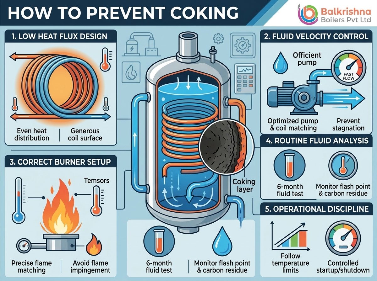
- Low Heat Flux Design: Specify a coil designed for low heat flux, meaning generous coil surface area relative to the firing rate. This is the design philosophy behind our three-pass and four-pass coil designs, which prioritize a larger heat transfer surface specifically to keep film temperatures well below the fluid’s cracking point.
- Adequate Fluid Velocity: Ensure the pump and coil are sized together to maintain fluid velocity within the manufacturer’s recommended range across the entire coil length — not just at the inlet.
- Appropriate Fluid Selection: Choose a thermal fluid rated for your actual operating temperature with a reasonable safety margin, not one operating close to its maximum film temperature limit. Mineral-based fluids typically suit operations up to 300°C, while synthetic fluids handle higher-temperature applications more reliably.
Our oil/gas fired thermic fluid heater and vertical four-pass FBC thermic fluid heater are both engineered around this low-heat-flux principle, and Balkrishna Boilers’ DELTAPAC and THERMPAC ranges apply the same coil design philosophy across their capacity bands.
5. Prevention Strategy #2: Correct Burner Setup and Combustion Control
For fuel-fired heaters, combustion tuning has a direct impact on coking risk:
- Proper Flame Shape and Length: The burner must be set up so the flame profile matches the combustion chamber geometry — a flame that’s too long or improperly shaped can impinge directly on coil sections not designed for that heat load.
- Correct Excess Air Ratio: Running with too little excess air causes incomplete combustion and can create localized hot flame zones; running with too much wastes fuel and can destabilize flame shape. Routine combustion analysis keeps this in the correct band.
- Stack Temperature Monitoring: A rising stack temperature over time — even with stable process output — is one of the earliest indirect indicators of coil fouling from either flue-gas-side soot buildup or fluid-side coking, and should trigger an inspection.
6. Prevention Strategy #3: Operational Discipline
Even a well-designed system can develop coking if operating practices aren’t followed consistently.
A. Never Exceed Rated Bulk Outlet Temperature
Resist the temptation to push process temperature above the unit’s rated maximum “to get a little more output.” The margin between bulk fluid temperature and film cracking temperature exists specifically to protect the coil — running consistently at the edge of that margin defeats the purpose.
B. Maintain Continuous, Adequate Flow
Never operate the burner with the circulating pump running below its rated flow, and ensure low-flow interlocks are correctly configured and tested — not bypassed for convenience during a busy production run.
C. Controlled Start-Up and Shutdown
Rapid heat-up or shutdown cycles stress the fluid and coil unevenly. Follow a gradual, controlled temperature ramp during start-up, as outlined in our installation best practices guide, and avoid abrupt load swings during normal operation wherever the process allows.
D. Avoid Frequent Load Cycling
Systems that cycle rapidly between high and low firing rates — particularly in processes with inconsistent heat demand — experience more thermal stress at the coil surface than systems running at a stable, moderate load. Where possible, use buffer or thermal storage strategies to smooth out demand spikes.
7. Prevention Strategy #4: Fluid Monitoring and Maintenance
Fluid condition is your earliest warning system for developing coking risk — but only if it’s actually monitored.
- Routine Fluid Analysis: Test thermal fluid every 6 months for viscosity, flash point, acid number, and carbon residue. A dropping flash point or rising carbon residue signals the fluid’s cracking temperature is decreasing, increasing coking risk even at normal operating temperatures.
- Timely Fluid Replacement: Don’t wait for visible performance loss to replace degraded fluid. With proper maintenance, mineral oils typically last 3-5 years and synthetic fluids 8-10 years — but fluid analysis, not the calendar alone, should guide the replacement decision.
- Filtration: Install and maintain fluid-side filtration to remove particulate contamination and early breakdown products before they circulate repeatedly through the hottest section of the coil.
- Periodic Coil Inspection: Where accessible, periodic borescope or endoscopic inspection of coil sections can catch early-stage coking before it shows up as a measurable efficiency loss.
8. How to Detect Coking Before It Becomes Serious
Watch for these early warning signs, which typically appear well before coking becomes visually obvious:
- Rising Stack Temperature at a stable firing rate and process load, indicating declining heat transfer efficiency.
- Increasing Fuel Consumption to maintain the same process temperature output.
- Widening Gap Between Inlet and Outlet Coil Temperatures beyond the system’s normal design differential.
- Slower Heat-Up Times during start-up compared to the unit’s historical performance.
- Fluid Analysis Trends showing declining flash point or rising carbon residue across consecutive testing intervals.
Catching any of these early allows for a planned coil cleaning or fluid change, rather than an unplanned shutdown when coking has already progressed to the point of visible tube damage — a scenario explored further in our article on common thermic fluid heater problems and their solutions.
9. What to Do If Coking Has Already Occurred
If inspection or performance data confirms coking has developed, the response depends on severity:
- Light Coking: Chemical cleaning using an approved coil-cleaning fluid, circulated through the system per manufacturer guidelines, can dissolve early-stage carbon deposits without requiring coil removal.
- Moderate Coking: Mechanical cleaning — physically removing and cleaning coil sections — may be necessary if chemical cleaning doesn’t restore adequate heat transfer performance.
- Severe Coking: In advanced cases with confirmed metallurgical stress or visible tube damage, partial or full coil replacement is the only safe option. Attempting to run a heater with a severely coked and structurally compromised coil section is a genuine safety risk.
In every case, the root cause identified through the diagnostic steps above must be corrected before returning the system to service — otherwise, a newly cleaned or replaced coil will simply begin coking again under the same conditions.
10. Industry Applications Where Coking Risk Runs Highest
Certain process industries run their thermic fluid heaters closer to design temperature limits or under more variable load conditions, making coking prevention especially important:
- Textile Processing: Stenter frames often demand rapid temperature response, increasing load-cycling stress — see our guide on thermic fluid heaters for textile processing for application-specific considerations.
- Plastics Processing: Precise, high-temperature mold and die heating leaves little margin for fluid degradation — our article on thermic fluid heater applications in the plastics industry covers the temperature stability requirements involved.
- Food Processing: Frying and deodorizing applications often run at sustained high temperatures for extended periods, making routine fluid monitoring especially critical — detailed further in thermic fluid heater applications in food processing plants.
11. Build Coking Prevention Into Your System From Day One
Coking is preventable — but only through a combination of correct design, disciplined operation, and consistent fluid monitoring. It’s far cheaper to specify a low-heat-flux coil and maintain a routine fluid analysis schedule than to face an unplanned coil replacement.
At Indian Boilers.com, every unit we design — from our electric thermic fluid heater to our vertical three-pass oil/gas fired models — is engineered around low-heat-flux coil design specifically to minimize coking risk over the system’s operating life. Our parent company, Balkrishna Boilers Pvt Ltd, backs this with over 25 years of field experience across more than 5,000 installations worldwide, including the VFF Series and PELLEPAC ranges built specifically for demanding, continuous-duty applications.
- Explore Our Thermic Fluid Heater Range: indianboilers.com/product-category/thermic-fluid-heater
- View the Full Balkrishna Boilers Range: balkrishn.com/thermic-fluid-heater.php
- Request a Fluid Analysis or Coil Inspection: Contact our technical team to schedule a system health check for your existing thermic fluid heater.