
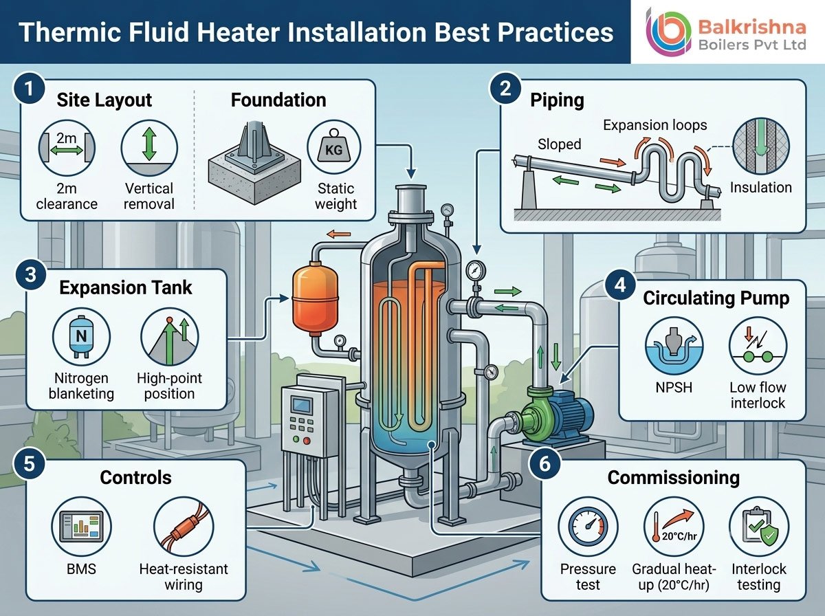
Thermic Fluid Heater Installation Best Practices
A thermic fluid heater is only as good as its installation. The unit itself might be correctly sized, correctly specified, and built to a high standard — but a poor site installation is where most early-life failures, safety incidents, and warranty claims originate. Piping laid out incorrectly, an undersized expansion tank, a missed nitrogen blanket, or a rushed commissioning sequence can turn a well-engineered thermic fluid heater into a recurring maintenance headache within the first year.
This guide lays out the installation best practices we follow across every project — from foundation planning to final commissioning — so plant engineers, EPC contractors, and maintenance teams have a clear checklist before, during, and after installation. If you’re still finalizing which unit to install, it’s worth first reading through our guide on thermic fluid heater capacity: how to choose the right size, since correct sizing is the foundation every installation decision below builds on.
1. Pre-Installation Planning: Getting the Groundwork Right
Before any equipment arrives on site, several planning decisions determine whether the installation goes smoothly.
A. Site Layout and Clearances
The heater needs adequate clearance on all sides for burner servicing, coil inspection, and emergency access. As a general rule:
- Allow at least 1.5-2 meters of clearance around the heater body for maintenance access.
- Ensure sufficient headroom above the unit for chimney routing and coil removal during future servicing.
- Position the unit so the burner front faces an open, unobstructed area — this is where servicing and adjustment happen most frequently.
Vertical models are often chosen specifically because they solve space constraints. If your plant has limited floor area, it’s worth comparing installation footprints across our vertical three-pass oil/gas fired thermic fluid heater and vertical four-pass FBC thermic fluid heater — both are engineered for compact plant footprints without compromising heat transfer efficiency. Balkrishna Boilers offers equivalent compact vertical ranges under the VTF Series and VTM Series.
B. Foundation Requirements
The heater foundation must be designed for the static weight of the unit plus the weight of the thermic fluid when the system is fully charged — not just the empty unit weight. A reinforced concrete foundation, sized according to the manufacturer’s general arrangement (GA) drawing, is standard. Skipping this step or using an undersized foundation is one of the most common causes of vibration-related coil and pump issues down the line.
C. Fuel Supply Planning
Fuel infrastructure needs to be finalized before installation day, not after. This includes:
- Liquid fuels (HSD, LDO, Furnace Oil): Storage tank sizing, day-tank placement, and fuel line routing with appropriate heat tracing for viscous fuels.
- Gaseous fuels (PNG, LPG, Biogas): Pressure regulation stations, leak detection points, and safety shut-off valves positioned per code.
- Solid fuels (Coal, Wood, Rice Husk, Briquettes): Fuel handling and feeding systems, ash removal access, and adequate combustion air supply.
If you haven’t finalized your fuel choice yet, our comparison of thermic fluid heater fuel options: coal, biomass, or gas breaks down the installation and operational trade-offs of each before you commit to site infrastructure.
2. Piping Design and Layout Best Practices
Piping design is where most thermic fluid systems succeed or fail long-term. Unlike water piping, thermal fluid piping has to account for thermal expansion, fluid velocity, and the risk of trapped air pockets or vapor locks.
A. Pipe Sizing and Velocity
Thermal fluid piping should be sized to maintain adequate flow velocity — typically in the range of 1.5 to 2.5 m/s in main headers — to prevent stagnation and localized overheating (film boiling) at the coil surface. Undersized piping increases pump head requirements and can starve distant heat users of adequate flow.
B. Slope and Air Elimination
All piping should be laid with a consistent slope (typically a minimum of 1:100) toward air-release points and the expansion tank. Thermal fluid systems are extremely sensitive to trapped air and vapor pockets — these create hot spots, cause pump cavitation, and accelerate fluid degradation at the point of the pocket. Every high point in the piping run should have a manual or automatic air vent.
C. Expansion Loops and Supports
Thermal fluid piping operates at high temperatures and undergoes significant linear expansion during heat-up. Piping runs need:
- Properly calculated expansion loops or expansion joints at regular intervals.
- Pipe supports that allow for thermal movement (spring hangers or sliding supports) rather than fixed rigid supports throughout.
- Anchor points positioned to control the direction of expansion, preventing stress on the heater’s coil connections.
D. Insulation
All hot piping, valves, and the heater body itself should be insulated with high-temperature mineral wool or equivalent insulation, finished with aluminum cladding. Proper insulation isn’t just about energy efficiency — it protects personnel from contact burns and reduces radiant heat load in the plant, which is directly tied to the efficiency gains covered in our article on how thermic fluid heaters improve energy efficiency.
3. Expansion Tank Installation
The expansion tank is one of the most misunderstood components in a thermic fluid system, yet it’s critical to both safety and fluid life.
A. Correct Positioning
The expansion tank must be installed at the highest point of the system, above the highest heat user, to ensure the entire system remains flooded and air cannot be drawn into the circulating loop.
B. Nitrogen Blanketing
A nitrogen blanket over the fluid surface in the expansion tank prevents oxidation of the thermal fluid — oxidation is one of the leading causes of premature fluid degradation, sludge formation, and coil fouling. The nitrogen supply should be regulated to maintain a slight positive pressure (typically 0.1-0.2 bar) without venting excessively.
C. Level Instrumentation
The expansion tank should have both a visual level gauge and an electronic low-level switch interlocked to the burner control system. If fluid level drops below the safe minimum — due to a leak or excessive fluid consumption — the burner should trip automatically. This ties directly into the interlocks discussed in our guide on thermic fluid heater safety precautions every operator should follow.
4. Circulating Pump Installation
The circulating pump is the heart of the system’s heat delivery, and improper installation here directly threatens coil life.
- Suction Conditions: Ensure adequate net positive suction head (NPSH) by keeping suction piping short, straight, and free of unnecessary fittings. Cavitation at the pump suction is a common cause of premature seal failure in thermal fluid pumps.
- Mechanical Seal Selection: Use mechanical seals rated for the specific fluid’s maximum operating temperature, with appropriate cooling arrangements if required by the seal manufacturer.
- Low-Flow Interlock: Every circulating pump should be paired with a flow switch interlocked to the burner — if circulation stops, the burner must shut down immediately to prevent the fluid from overheating and cracking inside the coil, a failure mode covered in detail in our article on signs of thermic fluid degradation and when to replace it.
5. Electrical and Control Panel Installation
- Panel Location: Install the control panel in a location protected from direct heat radiation, moisture, and dust, but within convenient sightline of the heater for operator monitoring.
- Instrumentation Wiring: All temperature sensors (inlet, outlet, and stack), pressure transmitters, and safety interlocks should be wired with adequately rated, heat-resistant cable, especially near the heater body.
- Burner Management System (BMS): Ensure the BMS is correctly configured for your specific fuel type and includes proper flame-failure detection, purge cycles, and ignition sequencing before first firing.
For electric-fired systems, installation differs meaningfully from combustion-fired units — if you’re installing an electric thermic fluid heater (part of our ELECTROPAC range, also available from Balkrishna Boilers under EDOPAC), electrical load calculations, dedicated feeder sizing, and heating element staging become the primary installation considerations instead of fuel and combustion air planning.
6. Chimney and Flue Gas Installation
For fuel-fired units, correct chimney design directly affects combustion efficiency and draft stability:
- Height and Diameter: The chimney must be sized per the manufacturer’s draft calculations — an undersized or incorrectly positioned chimney creates poor draft, incomplete combustion, and soot accumulation in the coil.
- Stack Temperature Monitoring: A stack temperature sensor should be installed to continuously monitor flue gas temperature, which is an early indicator of fouling or heat-transfer inefficiency on the fire side of the coil.
- Material Selection: For solid-fuel and biomass-fired units especially, chimney material must withstand higher particulate loads and potential condensation during startup and shutdown cycles.
7. Fluid Charging and Pre-Commissioning Checks
Before the system is charged with thermal fluid, complete the following checks:
- Pressure Testing: Hydro-test all piping joints and connections at the specified test pressure to confirm there are no leaks before introducing thermal fluid.
- Flushing: Flush the entire piping system to remove construction debris, welding slag, and dust — contaminants left in the system will circulate continuously once fluid charging begins and can foul the coil.
- Moisture Removal: Dry out the system thoroughly before charging with thermal fluid. Any residual moisture will flash to steam during initial heat-up, causing dangerous pressure spikes and fluid foaming.
- Initial Fluid Fill: Charge the system slowly through the expansion tank, allowing air to escape through vents at each high point as the fluid fills the loop.
8. Commissioning and Initial Start-Up
A. Cold Circulation
Before first firing, run the circulating pump on cold fluid to confirm proper flow distribution to all heat users, verify there are no leaks under dynamic conditions, and bleed any remaining trapped air.
B. Gradual Heat-Up
Thermal fluid systems should never be heated up rapidly. A controlled, gradual temperature ramp — typically no faster than 20-25°C per hour during initial commissioning — allows the fluid, piping, and coil to expand uniformly and avoids thermal shock at welded joints.
C. Moisture Boil-Off
During the initial heat-up, hold the system temporature briefly at around 100-110°C to boil off any residual moisture in the fluid before continuing to ramp toward operating temperature. This step is often skipped under time pressure, but skipping it is one of the most common causes of early fluid foaming and pump cavitation.
D. Interlock Testing
Before handing the system to operations, test every safety interlock individually — low-flow trip, high-temperature cutoff, low-level cutoff, and flame failure — to confirm each one functions correctly under simulated fault conditions.
9. Common Installation Mistakes to Avoid
Across hundreds of installations, the same avoidable mistakes show up repeatedly:
- Undersized expansion tanks that can’t accommodate full thermal expansion of the fluid volume, leading to overflow or air ingress.
- Missing or poorly maintained nitrogen blanketing, accelerating fluid oxidation from day one.
- Rigid pipe supports that don’t account for thermal expansion, leading to stress cracks at welded joints within months.
- Skipping the moisture boil-off step during commissioning, causing foaming and cavitation issues that persist for the life of the fluid charge.
- Incorrect chimney sizing, leading to poor draft and combustion inefficiency that’s difficult to diagnose after the fact.
Many of these issues surface later as operational problems rather than obvious installation defects — our article on common thermic fluid heater problems and their solutions traces several of these back to installation-stage root causes.
10. Post-Installation: Setting Up for Long-Term Reliability
Once commissioning is complete, a few final steps set the system up for years of trouble-free operation:
- Document As-Built Piping: Keep accurate as-built drawings of the final piping layout, including all air vent and drain point locations, for future maintenance reference.
- Baseline Fluid Analysis: Take an initial fluid sample immediately after commissioning to establish a baseline for future fluid condition monitoring.
- Operator Training: Ensure plant operators are trained on start-up, shutdown, and emergency procedures specific to your installed model and fuel type.
- Maintenance Schedule: Establish a maintenance calendar covering burner servicing, coil inspection, and fluid analysis — typically every 6 months — from day one of operation.
11. Work With Installation Specialists
A correctly engineered thermic fluid heater can still underperform — or fail early — if installation shortcuts are taken. At Indian Boilers.com, we provide end-to-end installation support, including piping design review, commissioning supervision, and operator training, for every unit we supply — from compact oil/gas fired thermic fluid heaters to large custom-engineered systems.
Our parent company, Balkrishna Boilers Pvt Ltd, brings over 25 years of installation experience across more than 5,000 installations worldwide, with proven ranges including DELTAPAC, THERMPAC, and PELLEPAC — engineered specifically for straightforward, reliable site installation.
- Explore Our Thermic Fluid Heater Range: indianboilers.com/product-category/thermic-fluid-heater
- View the Full Balkrishna Boilers Range: balkrishn.com/thermic-fluid-heater.php
- Get an Installation Quote: Contact our technical team with your site layout and fuel requirements for a customized installation plan.