
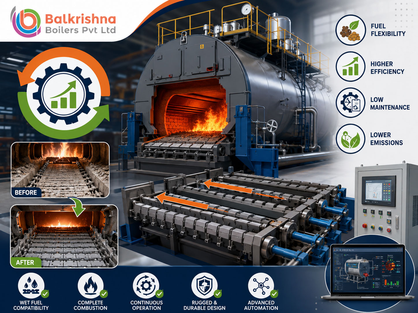
Retrofitting to a Reciprocating Grate: The Engineering Path for Existing Plants
Replacing an entire boiler is rarely the first option a plant manager wants to consider — it means major capital expenditure, an extended shutdown, and civil work that disrupts production for weeks. For plants running legacy combustion systems that are structurally sound but combustion-obsolete, there’s a genuinely viable middle path: retrofitting the combustion chamber itself with modern reciprocating grate technology, while keeping the existing pressure vessel in service.
This guide covers the engineering roadmap for exactly that retrofit — what makes a plant a genuine candidate, the technical steps involved, and the realistic performance and financial case. If you’re specifying a new-build reciprocating grate system rather than retrofitting an existing one, our reciprocating grate mechanics guide and reciprocating grate fuel guide cover that ground in depth.
1. Why Legacy Combustion Systems Become a Genuine Liability
Static grates, manual dumping grates, older traveling grates, and even fluidized bed systems each carry specific limitations that compound over time as fuel quality and cost pressures shift.
Static and manual grates — repeated opening of fire doors for manual stoking or raking introduces uncontrolled cold ambient air into the furnace, destabilizing the air-to-fuel ratio and dropping furnace temperature with every intervention. Manual ash cleaning compounds this, causing periodic thermal drops and fluctuating steam pressure that a continuous automated system wouldn’t experience.
Older traveling (chain) grates — because the fuel bed stays largely static relative to the grate bars as it travels from feed to discharge, moisture above roughly 30-35% causes the fuel bed to form a crust, trapping moisture underneath and burning late — a direct cause of elevated unburned carbon in bottom ash. These systems also demand fairly uniform fuel sizing; irregular agro-waste, large wood chips, or fibrous crop residue can jam feeders or create uneven combustion lanes.
Bubbling fluidized bed combustion (BFBC) — genuinely efficient for uniform, low-moisture, low-ash fuels like crushed coal or rice husk, but heavy-ash or high-alkali fuels — cotton stalk, mustard straw, sand-contaminated wood waste — can agglomerate the silica bed, causing defluidization, frequent bed de-ashing shutdowns, and high auxiliary power draw from fluidizing fans.
2. Why Reciprocating Grate Retrofit Solves These Problems Simultaneously
A reciprocating grate’s stepped design — alternating rows of fixed and moving high-alloy bars, driven by automated hydraulic cylinders producing rhythmic pushing and tumbling motion — addresses three problems at once, a genuine advantage over patching each legacy limitation separately:
Forced thermal back-mixing — moving elements continuously push burning char backward beneath incoming cold, wet raw fuel, transferring intense radiant heat by conduction that rapidly evaporates surface moisture and drives fast ignition, directly solving the traveling grate’s crusting problem.
Genuine fuel flexibility — the same mechanism handles high-moisture sugarcane bagasse above 50% moisture through to low-density crop straws, rice husk, sawdust, pellets, and industrial wood waste without mechanical modification, solving the traveling grate’s uniform-sizing requirement.
Continuous self-cleaning — the shearing action constantly breaks up fused ash lumps and clinkers, preventing bed agglomeration and ensuring smooth discharge without requiring combustion shutdowns — directly solving BFBC’s defluidization vulnerability with alkali-rich fuels.
3. Is Your Plant Actually a Retrofit Candidate?
Not every legacy boiler should be retrofitted — a thorough engineering inspection of existing structural components has to happen before committing to the project. A plant is a genuine candidate when it meets several criteria together:
Sound pressure parts — the steam drum, mud drum, water wall tubes, and convective bank tubes need to pass ultrasonic thickness gauge testing and radiographic evaluation. Where these core pressure parts test healthy, a retrofit can genuinely extend the boiler’s service life by a further decade or more, capturing most of the value of new equipment at a fraction of full replacement cost.
Genuine fuel procurement variability — facilities that need to switch fuel sources seasonally (rice husk for part of the year, mustard straw for another stretch, wood chips or briquettes during monsoon) benefit most directly from the fuel flexibility a reciprocating grate provides.
Derated steam performance — where the boiler can no longer reach its original design capacity because current fuel supply carries higher moisture or lower bulk density than the boiler’s original design fuel assumed.
Rising operating costs — climbing grid power draw, manual ash-handling labor, and auxiliary fossil fuel support costs that a modern combustion system would meaningfully reduce.
4. The Engineering Roadmap
A properly executed retrofit follows a structured technical sequence, not an ad-hoc equipment swap:
Step 1 — Fuel and volatile combustion field analysis. Biomass typically carries 70-80% volatile matter on a dry, ash-free basis, releasing almost instantly when heated — the retrofit design has to account for this gas volume by calculating stoichiometric air requirements specific to the actual fuel blend the plant will run.
Step 2 — Grate area scaling. Because biomass carries lower bulk density and calorific value than coal, the new grate surface area needs correct proportioning based on the Grate Heat Release Rate (GHRR, measured in kcal/m²·hr), ensuring the grate provides enough length and width to fully dry, gasify, and burn out fuel before it reaches ash discharge.
Step 3 — Furnace volume expansion. To prevent unburned volatiles entering the convective bank and causing secondary combustion that damages economizer or superheater tubes, combustion chamber volume often needs adjustment — raising the boiler structure, deepening the foundation pit, or modifying the water wall profile to extend furnace residence time to a range that supports complete combustion at appropriate temperature.
Step 4 — Air staging reconfiguration. Legacy systems commonly route a large majority of combustion air under the bed, which causes rapid ash carryover and elevated particulate emissions on biomass fuel. A proper retrofit splits air into a staged configuration — roughly 40-50% primary under-grate air through independently zoned dampers for drying and gasification control, with the remainder as secondary over-fire air injected at high velocity above the bed to drive complete volatile combustion.
Step 5 — Hydraulic and control integration. The mechanical grate pairs with a heavy-duty hydraulic power pack, with variable stroke speed controlled through a central PLC panel integrated with real-time oxygen sensors in the flue gas duct — automating combustion tuning rather than relying on fixed manual settings.
5. What a Well-Executed Retrofit Typically Delivers
The table below represents the kind of performance shift a well-engineered retrofit — converting an older traveling or chain grate system running on biomass to a modern reciprocating grate — can typically achieve. These figures are representative of realistic outcomes for a properly executed retrofit, not guaranteed results for any specific installation; actual performance depends on your existing boiler’s condition, fuel profile, and how completely each engineering step above is executed.
| Operational Parameter | Typical Pre-Retrofit (Legacy Grate) | Typical Post-Retrofit (Reciprocating Grate) |
|---|---|---|
| Fuel moisture tolerance | Up to 30-35% | Up to 50-55% |
| Overall thermal efficiency | Roughly 68-72% | Roughly 82-85% |
| Unburned carbon in bottom ash | 8-14% | Under 2.5% |
| Steam output stability | Fluctuating | Meaningfully more stable |
| Turn-down ratio | Roughly 1:2 | Roughly 1:4 |
| Maintenance shutdown frequency | Frequent (jamming, clinker fusion) | Meaningfully reduced (self-cleaning grate) |
6. The Financial Case: A Framework, Not a Fixed Number
The financial justification for a retrofit rests on a few genuine, structural pillars, though the exact magnitude depends entirely on your specific plant.
Fuel cost savings — a meaningful efficiency improvement translates directly into reduced daily fuel consumption for the same steam output; the exact tonnage saved depends on your current capacity and baseline efficiency, so it’s worth calculating using your actual numbers rather than a generic figure.
Lower-cost multi-fuel sourcing — the ability to source cheaper regional agricultural waste (loose mustard straw, un-chopped bagasse, rice husk) instead of premium wood pellets or high-grade coal genuinely lowers fuel cost, though the savings depend on local fuel market pricing at the time.
Reduced auxiliary power and maintenance — automated hydraulic drives draw meaningfully less power than high-pressure fluidizing fans or continuously-tensioned chain drives, and reduced clinker damage cuts down on refractory patching and associated downtime.
Payback period genuinely varies by plant capacity and fuel cost differential — rather than quoting a fixed timeline that won’t reflect your specific situation, we’d recommend building your own calculation using your current fuel costs and realistic post-retrofit efficiency gains, following the same methodology as our biomass ROI framework.
7. What a Proper Retrofit Partner Should Deliver
Executing a combustion retrofit on a living manufacturing asset genuinely demands specialized design capability and field execution experience — this isn’t a project to hand to a generalist contractor.
High-chromium grate metallurgy — grate bars cast from advanced high-chromium alloy formulations for structural integrity, minimal thermal distortion, and wear resistance against abrasive biomass ash.
Zoned under-grate air plenums — a re-engineered windbox assembly divided into separate, air-sealed compartments, letting operators fine-tune drying, combustion, and cooling air zones independently based on current fuel conditions.
Full automation integration — SCADA and PLC systems with real-time fuel-bed optimization, automated hydraulic stroke control, VFD fan modulation, and continuous emissions monitoring.
Complete field execution support — from initial pressure part thickness inspection through dismantling of the old grate, structural foundation work, refractory reconstruction, and final commissioning, ideally managed by one accountable engineering team rather than coordinated across multiple contractors.
Conclusion: A Genuine Middle Path Between “Live With It” and “Replace Everything”
For plants with structurally sound pressure parts but combustion-obsolete grate technology, a reciprocating grate retrofit offers a genuinely viable path to modern fuel flexibility and efficiency without the capital cost and extended shutdown of full boiler replacement. The key is proper candidate assessment upfront — verifying pressure part integrity through real testing, not assumption — before committing to the engineering work.
Balkrishna Boilers Pvt Ltd delivers turnkey retrofit engineering, from structural assessment through commissioning. Explore our biomass and STEAMPOWER range on IndianBoilers.com or Balkrishn.com.
Wondering whether your existing boiler is a genuine retrofit candidate? Contact our combustion engineering team for a technical evaluation of your plant’s current system.
Related Reading
- Reciprocating Grates: The Mechanical Engineering Behind Clinker-Proof Biomass Combustion
- Which Biomass Fuel Actually Suits Your Reciprocating Grate? A Fuel-by-Fuel Breakdown
- The Biomass Boiler ROI Calculation: A Framework, Not Just a Percentage
- Vibrating Grate Boiler vs Reciprocating Grate Boiler: Which Technology Delivers Better Performance?
- Traveling Grate Boilers for Sugar Mills: The Ultimate Engineering Guide