Water‑Tube Boiler Definition and Basic Concept
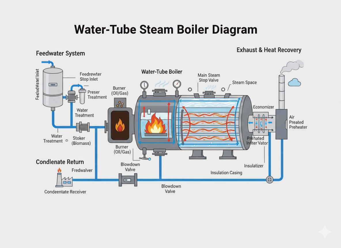
A water‑tube steam boiler is a steam generator where water and steam travel through a network of tubes connected to one or more drums, and the heat source is outside these tubes. Water enters the tubes, absorbs heat from the surrounding hot gases, turns into steam, and is then collected and separated in the steam drum. Because the water is confined in small‑diameter tubes, these boilers safely handle very high pressures and temperatures.
In contrast to fire‑tube boilers (where hot gases are inside tubes and water is in the shell), water‑tube designs put the water in the tubes and the flue gas in the furnace chamber and gas passes, improving heat transfer. This configuration supports faster circulation, higher steaming rates, and better control over steam quality.
Main Components of a Water‑Tube Boiler
Key parts of a typical water‑tube steam boiler include:
- Steam drum: Located at the top, it receives the steam–water mixture from the riser tubes, separates dry steam from water, and serves as a reservoir for steam and boiler water.
- Mud drum or lower drum: Placed at the bottom, it collects heavier water and sludge and distributes water to the lower ends of the tubes; it often has blowdown connections to remove impurities.
- Riser tubes (water tubes): Tubes that surround the furnace and absorb radiant and convective heat; water inside these tubes boils and forms a steam–water mixture that rises to the steam drum.
- Downcomers: Larger pipes that carry relatively cool, dense water from the steam drum down to the mud drum, completing the natural circulation loop.
- Furnace or combustion chamber: The enclosed space where fuel (oil, gas, coal, biomass, etc.) and air are burned, producing the high‑temperature flue gases that heat the tubes.
- Burners or stokers: Devices that mix fuel and air and ignite the flame; their design controls combustion intensity and efficiency.
- Headers: Manifolds that collect and distribute water or steam to groups of tubes, improving flow distribution.
- Superheater (in many units): Additional tube banks in the hot‑gas path that raise steam temperature above saturation to produce superheated steam for turbines.
- Economizer: Heat‑recovery section in the flue‑gas path that preheats incoming feedwater using residual exhaust heat, increasing overall efficiency.
- Air preheater: Transfers heat from flue gas to combustion air, improving fuel burning efficiency and lowering fuel consumption.
- Mountings and accessories: Safety valves, pressure gauges, water level indicators, feedwater regulators, blowdown valves, and control systems ensure safe and reliable operation.
Working Principle: Natural Circulation Loop
The fundamental working principle of a water‑tube boiler is natural or forced circulation based on density difference between hot and cold water. When water inside the furnace‑exposed tubes is heated, steam bubbles form, reducing density of the mixture; this lighter mixture rises through riser tubes to the steam drum. Cooler, denser water in the downcomers flows downward to replace it, creating a continuous loop.
In the steam drum, separators, baffles, or demisters remove moisture from the steam–water mixture. Dry saturated steam collects at the top and is routed to the outlet header or superheater. The separated water, still hot but mostly liquid, flows back via downcomers to the lower drum and again through the furnace‑side tubes, sustaining circulation without mechanical pumps in natural‑circulation designs.
Step‑by‑Step Operation
- Feedwater supply: Treated feedwater enters the system, usually after passing through an economizer where it is preheated by exhaust gases. A feedwater pump raises its pressure above boiler operating pressure and delivers it to the steam drum or lower drum.
- Water distribution: From the drum, water flows down the downcomers into the lower drum or lower headers. From there, it is distributed into the lower ends of the furnace tubes and other generating tubes.
- Heat absorption in furnace: Fuel and air are mixed and burned in the furnace. The resulting hot gases (often above 1000–1500 °C near the flame) flow over the tube surfaces, transferring heat by radiation and convection. Water in the tubes absorbs this heat; its temperature rises to saturation, and boiling begins.
- Riser flow and steam generation: As boiling occurs, steam bubbles form in the tubes, decreasing the density of the water–steam mixture. This lighter mixture rises through the riser tubes into the steam drum. Simultaneously, cooler water in downcomers descends, creating the natural circulation pattern.
- Steam–water separation: In the steam drum, internal devices (baffles, cyclone separators, scrubbers) slow the flow and separate steam from water. Water droplets fall back into the water mass, while dry saturated steam accumulates in the upper part of the drum.
- Superheating (if provided): Saturated steam may pass through a superheater bank located in a hotter zone of the flue‑gas path, where its temperature is raised without increasing pressure, producing superheated steam suitable for turbines or long steam lines.
- Steam delivery: The final steam leaves the boiler through the main steam stop valve and is sent to process equipment, turbines, heating systems, or other consumers. Pressure‑control and safety devices ensure it remains within design limits.
- Flue‑gas heat recovery and exhaust: After leaving the furnace, flue gases pass over superheater, economizer, and air preheater surfaces, transferring remaining heat to steam, feedwater, and air. Finally, cooled gases exit through the chimney.
- Blowdown and impurity control: Dissolved and suspended solids concentrate in the boiler water as steam is generated. Periodic or continuous blowdown from the mud drum and sometimes the steam drum removes sludge and maintains water quality to prevent scaling and corrosion.
- Condensate return: In many plants, steam after doing work condenses and is collected as condensate. This hot condensate is returned to the feedwater tank, reducing the energy required to raise water back to saturation temperature and lowering make‑up water demand.
Types and Configurations
Several configurations of water‑tube boilers are used depending on capacity, pressure, and layout constraints:
- D‑type boilers: Have a large steam drum on top and a smaller mud drum below, forming a “D” shape with the furnace; widely used in marine and industrial service because of compactness and high steaming rate.
- A‑type and O‑type boilers: Variations in drum and furnace arrangement that optimize footprint, maintenance access, and gas‑flow pattern.
- Integral furnace or packaged units: Factory‑assembled boilers with integrated burners, fans, and controls, designed for fast installation and lower site work.
- Once‑through or forced‑circulation units: Use pumps to force water through tubes in a single pass, suitable for very high pressures (supercritical units in power plants) where natural circulation is inadequate.
- Utility water‑tube boilers: Very large multi‑drum or once‑through designs used in thermal power stations, often with extensive superheater, reheater, and economizer sections.
These variations all share the same core idea: water inside tubes, gas outside, and circulation driven by density difference or pumps.
Advantages of Water‑Tube Steam Boilers
Water‑tube boilers are preferred in many high‑demand applications because of several key advantages:
- High pressure and high capacity: Small water volume in tubes can safely sustain very high pressures and large steaming rates, making them ideal for power generation and large industrial plants.
- Rapid response: Because the water volume is relatively low and heat transfer area is large, they respond quickly to load changes, helping maintain consistent steam conditions.
- Better heat transfer and efficiency: Large total tube surface and the ability to add economizers and air preheaters yield high thermal efficiencies and lower fuel consumption.
- Improved safety margin: A tube failure usually affects only a small portion of water inventory and can often be contained; the risk of catastrophic shell rupture is lower than in large fire‑tube shells.
- Flexible layout: Multiple drums, headers, and tube banks can be arranged to fit restricted spaces or special furnace shapes, and different fuels can be accommodated.
Limitations and Considerations
Despite these strengths, water‑tube boilers have some limitations that must be managed:
- Higher initial cost: The complex network of tubes, drums, and accessories typically makes them more expensive than simple fire‑tube units of small capacity.
- More demanding water quality: Narrow tubes and high heat flux require good feedwater treatment and strict control of dissolved solids to avoid scaling or tube overheating.
- Skilled operation and maintenance: Operators must understand circulation, drum levels, and firing control; poor practices can lead to tube failures or unsafe conditions.
- Sensitive to load and flow issues: Inadequate circulation, blocked tubes, or rapid load swings can cause local overheating, so design and control systems must be properly engineered.
Typical Industrial Applications
Because of their performance characteristics, water‑tube steam boilers are used in:
- Thermal power plants (utility boilers feeding steam turbines).
- Refineries, petrochemical plants, and chemical processing units.
- Large textile, paper, and sugar mills needing high‑pressure, high‑volume steam.
- Marine propulsion plants on large ships.
- District heating and cogeneration plants using combined heat and power schemes.
In all these settings, the ability to generate large quantities of high‑pressure steam efficiently and reliably makes water‑tube boilers a core part of the energy infrastructure.
For any inquiries regarding returns, refunds, or warranty claims, please contact the IndianBoilers.com Customer Service and Technical Support team immediately.