
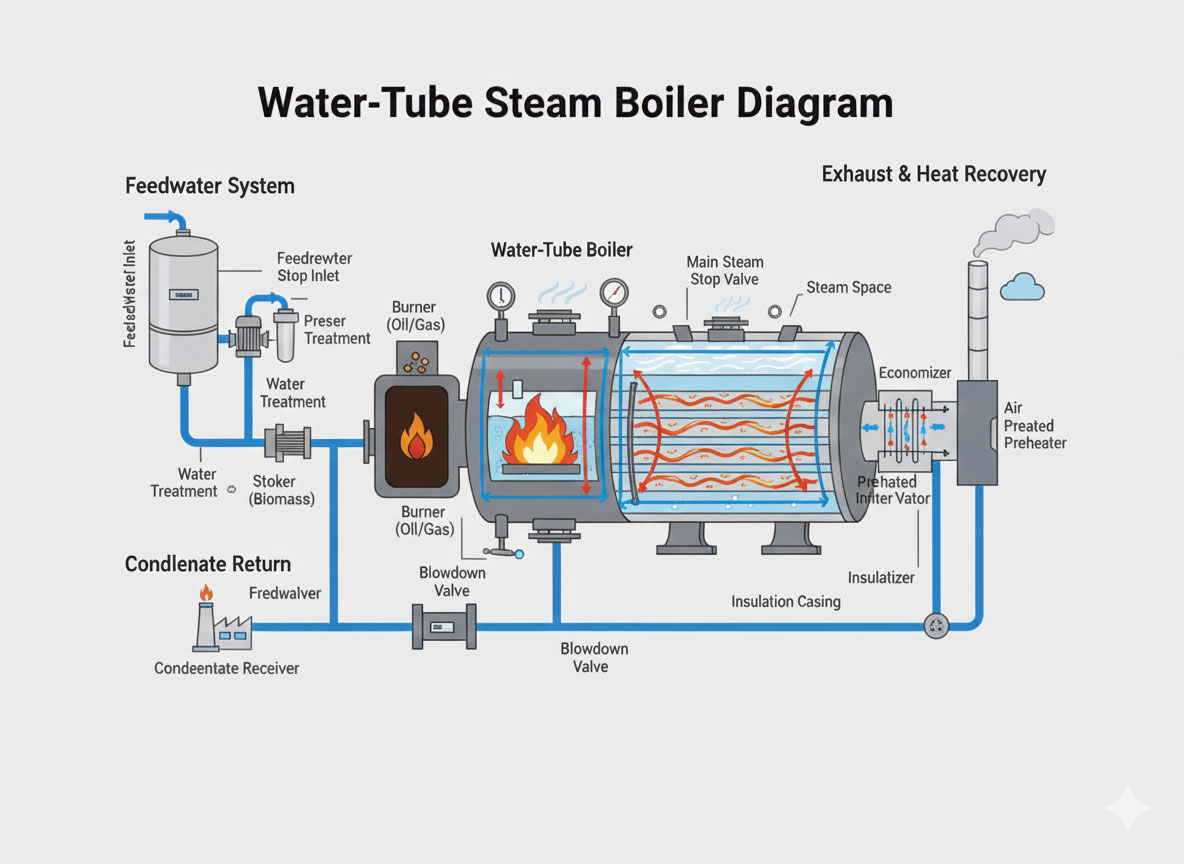
If you’ve read our comparison of water-tube vs. fire-tube boilers, you already know water-tube design wins where high pressure and fast load response matter most. This piece goes a level deeper — into the actual mechanics of how a water-tube boiler generates steam, what each component does, and why the physics of density difference alone can drive circulation without a single pump in many designs.
A water-tube steam boiler is, at its core, a network of tubes connected to one or more drums, with water flowing inside the tubes and the heat source — burning fuel — positioned outside them. Water enters the tube network, absorbs heat from the surrounding hot gases, converts to steam, and is collected and separated in a steam drum above. Because the water inventory is confined to small-diameter tubes rather than one large shell, this design safely handles pressures that would be structurally impractical in a fire-tube vessel of comparable size.
1. The Component Map: What’s Actually Inside
Understanding a water-tube boiler starts with knowing what each part does — because the working principle only makes sense once you can picture the physical path water actually travels.
Steam drum — Positioned at the top, this receives the steam-water mixture arriving from the riser tubes, separates dry steam from remaining water, and serves as a reservoir for both steam and boiler water.
Mud drum (lower drum) — Sits at the bottom, collecting heavier water and accumulated sludge, and distributes water to the lower ends of the tube network. Blowdown connections here are what physically remove concentrated impurities from the system.
Riser tubes (water tubes) — These surround the furnace directly, absorbing radiant and convective heat. Water inside boils and forms a steam-water mixture that rises toward the steam drum — this is where the actual heat-to-steam conversion happens.
Downcomers — Larger-diameter pipes carrying cooler, denser water from the steam drum back down to the mud drum, completing the circulation loop that keeps the whole system moving.
Furnace/combustion chamber — The enclosed space where fuel and air burn, generating the high-temperature flue gases — often exceeding 1000–1500°C near the flame — that heat the tube surfaces.
Burners or stokers — Control the mixing and ignition of fuel and air; their design directly determines combustion intensity and efficiency.
Headers — Manifolds distributing water or steam across groups of tubes, ensuring even flow distribution rather than uneven heating across the tube bank.
Superheater — Present in many designs, this additional tube bank sits in the hot-gas path and raises steam temperature above saturation point without increasing pressure — essential for turbine applications and long steam distribution runs where condensation inside the line would otherwise be a problem.
Economizer — Recovers residual heat from exhaust flue gas to preheat incoming feedwater before it enters the system, a straightforward efficiency gain that costs nothing to operate once installed.
Air preheater — Transfers remaining flue gas heat to incoming combustion air, further improving fuel-burning efficiency.
Mountings and accessories — Safety valves, pressure gauges, water level indicators, feedwater regulators, blowdown valves, and control systems that collectively keep the system operating safely within design limits.
2. The Physics Behind Natural Circulation
Here’s the part that genuinely surprises people the first time they understand it: many water-tube boilers move water through the entire system continuously without any mechanical pump, relying purely on the density difference between hot and cold water.
When water inside the furnace-exposed riser tubes heats up, steam bubbles begin forming within it, which reduces the overall density of that water-steam mixture. Because it’s now lighter than the surrounding water, it rises naturally through the riser tubes toward the steam drum — the same basic principle that makes a hot air balloon rise, just applied to a liquid-vapor mixture inside a sealed tube.
As that lighter mixture rises and exits into the steam drum, cooler, denser water in the downcomers flows downward to replace it, drawn by that same density differential. This creates a continuous, self-sustaining loop: hot, low-density water and steam rising through the risers, cool, high-density water descending through the downcomers, over and over, entirely driven by physics rather than a mechanical pump.
In the steam drum itself, internal devices — baffles, cyclone separators, or scrubbers — slow the incoming flow enough to separate steam from any remaining water droplets. Water falls back into the drum’s water mass; dry, saturated steam collects at the top and moves onward to the outlet or superheater.
3. The Full Path, Step by Step
- Feedwater enters the system — typically after passing through the economizer for preheating, then a feedwater pump raises pressure above boiler operating pressure before delivery into the drum system.
- Water distributes downward — from the steam drum, through downcomers, into the mud drum and lower headers, then out to the lower ends of the tube network.
- Heat absorption begins in the furnace — fuel and air combust, and the resulting hot gases transfer heat by radiation and convection into the water flowing through the surrounding tubes.
- Boiling and riser flow — as the water reaches saturation temperature and begins boiling, steam bubbles reduce the mixture’s density, and it rises through the riser tubes into the steam drum, while cooler downcomer water descends to replace it.
- Steam-water separation — internal drum devices separate dry steam from any remaining water, with droplets falling back into the water mass.
- Superheating, where present — saturated steam passes through a superheater bank in a hotter zone of the flue-gas path, raising its temperature without raising pressure.
- Steam delivery — finished steam exits through the main stop valve to process equipment, turbines, or heating systems, with pressure control and safety devices maintaining design limits throughout.
- Flue gas heat recovery — after leaving the furnace, exhaust gases pass over the superheater, economizer, and air preheater in sequence, giving up remaining heat before exiting through the chimney.
- Blowdown and impurity control — periodic or continuous blowdown from the mud drum (and sometimes the steam drum) removes concentrated dissolved and suspended solids, preventing the scaling and corrosion that would otherwise accumulate.
- Condensate return — in many plants, steam that has done its work condenses downstream and returns to the feedwater system, reducing both the energy needed to reheat it and overall make-up water demand.
4. Configurations Worth Knowing
Water-tube design isn’t a single fixed layout — several configurations exist depending on capacity, pressure, and space constraints:
D-type boilers — A large steam drum on top paired with a smaller mud drum below, forming a characteristic “D” shape around the furnace. Compact and high-steaming-rate, which is why this configuration shows up frequently in both marine and industrial service.
A-type and O-type boilers — Variations in drum and furnace arrangement optimized for footprint, maintenance access, or specific gas-flow patterns.
Integral furnace / packaged units — Factory-assembled with burners, fans, and controls already integrated, designed to minimize on-site installation work and shorten commissioning time.
Once-through / forced-circulation units — Use pumps to force water through in a single pass rather than relying on natural circulation, suited to the very high pressures — including supercritical conditions — found in large power generation applications where natural circulation alone can’t reliably move enough water.
Utility-scale water-tube boilers — Very large multi-drum or once-through designs used in thermal power stations, typically with extensive superheater, reheater, and economizer sections layered together.
All of these variations share the same fundamental idea underneath: water inside the tubes, gas outside, and circulation driven either by density difference or by pumps.
5. What This Design Genuinely Gets You
High pressure and high capacity — the small water volume confined within tubes tolerates very high pressures and steaming rates safely, which is precisely why this design dominates power generation and large industrial plants.
Rapid load response — the relatively low water volume combined with large total heat transfer area means the system responds quickly to demand changes, holding steam conditions steady even through load swings.
Strong heat transfer and efficiency — the large total tube surface area, paired with economizer and air preheater integration, drives high thermal efficiency and lower fuel consumption per unit of steam produced.
Improved safety margin — because a single tube failure affects only a small portion of total water inventory, the risk profile is meaningfully better than the catastrophic-rupture risk associated with a large fire-tube shell operating at the same pressure.
Layout flexibility — multiple drums, headers, and tube banks can be arranged to fit constrained sites or unusual furnace shapes, and the design accommodates a wide range of fuel types.
6. What It Costs You
Higher initial investment — the complex network of tubes, drums, and accessories generally makes water-tube systems more expensive than a simple fire-tube unit of comparable small capacity.
More demanding water treatment — narrow tubes and high heat flux require disciplined feedwater treatment and tight control over dissolved solids, since scaling or fouling in a water-tube system has more immediate consequences than in a large-volume fire-tube shell.
Skilled operation requirements — operators genuinely need to understand circulation behavior, drum levels, and firing control; poor operating practice here carries more risk than it would in a simpler fire-tube design.
Sensitivity to flow disruption — inadequate circulation, tube blockage, or rapid load swings beyond design tolerance can cause localized overheating, which is why proper engineering of both the design and its control systems matters more here than in more forgiving designs.
7. Where This Design Actually Gets Deployed
Water-tube boilers are the design of choice across thermal power plants feeding steam turbines, refineries and petrochemical processing, large textile, paper, and sugar mills needing high-pressure, high-volume steam, marine propulsion on large vessels, and district heating or cogeneration plants running combined heat and power schemes. In every one of these settings, the ability to generate large quantities of high-pressure steam reliably is the deciding factor — not cost, not simplicity, but raw capability at scale.
8. Where Electric Technology Fits Into This Picture
It’s worth noting that everything described above — drums, riser tubes, downcomers, superheaters — exists specifically to manage combustion heat transfer efficiently at high pressure. Electric boiler technology sidesteps this entire mechanical architecture: ELECTROMAX – Electric IBR Steam Boiler achieves comparable rapid load response and pressure stability through staged resistance elements, with no furnace, no flue gas path, and no combustion-driven circulation physics to engineer around at all. For applications where the driving requirement is really responsiveness and pressure stability rather than raw multi-hundred-tonne-per-hour capacity, it’s worth evaluating whether electric technology solves the same problem more simply. Our complete guide to industrial electric steam boilers covers that comparison directly.
For large-capacity, biomass-fired water-tube applications specifically, our STEAMGEN – Wood/Briquette Fired Steam Boiler applies this design architecture at industrial scale.
Conclusion: The Design That Makes High-Pressure Steam Practical
Water-tube design solves a genuine engineering problem — generating large volumes of high-pressure steam safely — through a deceptively elegant mechanism: small water volumes in tubes, density-driven circulation, and a component architecture built to recover as much heat as possible along the way. Understanding that mechanism, not just the pressure and capacity numbers it enables, is what separates a genuinely informed equipment decision from a spec-sheet comparison.
Balkrishna Boilers Pvt Ltd manufactures water-tube systems including our STEAMGEN line, alongside the full electric range that solves similar responsiveness requirements without combustion. Explore the complete range on IndianBoilers.com or Balkrishn.com.
Have a high-pressure, high-capacity steam requirement to discuss? Contact our engineering team for a consultation matched to your specific pressure and capacity needs.
Related Reading
- Water Tube vs Fire Tube Steam Boilers: Key Differences Explained
- What Is a Steam Boiler? Definition, Working, and Types
- The Complete Guide to Industrial Electric Steam Boilers
- From Turbines to Tire Curing: How Steam Actually Does Work in Industry
- The Steam Boiler Buyer’s Guide: Choosing Steam Boilers in India